Project update 2 of 4
Getting Started Tutorial
by Deepak Khatri, Anuranan Kakati, Krishnanshu Mittal, Rup Jyoti Bharadwaj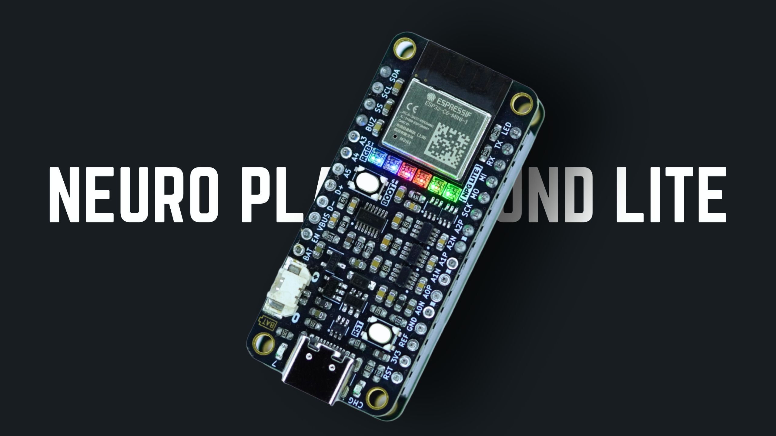
What Is Neuro PlayGround Lite?
This is Neuro PlayGround Lite, a pocket-sized bio-physiological sensing device with a 3-6-channel BioAmp that records EEG (brain waves), ECG (heartbeats), EOG (eye movements), and EMG signals (muscle activity). It streams data over multiple wireless protocols like BLE, Zigbee, Wi-Fi, or Thread for mesh networking It also offers FeatherWing-style expandability for plug-and-play HCI and BCI projects.
NPG Lite Technical Overview
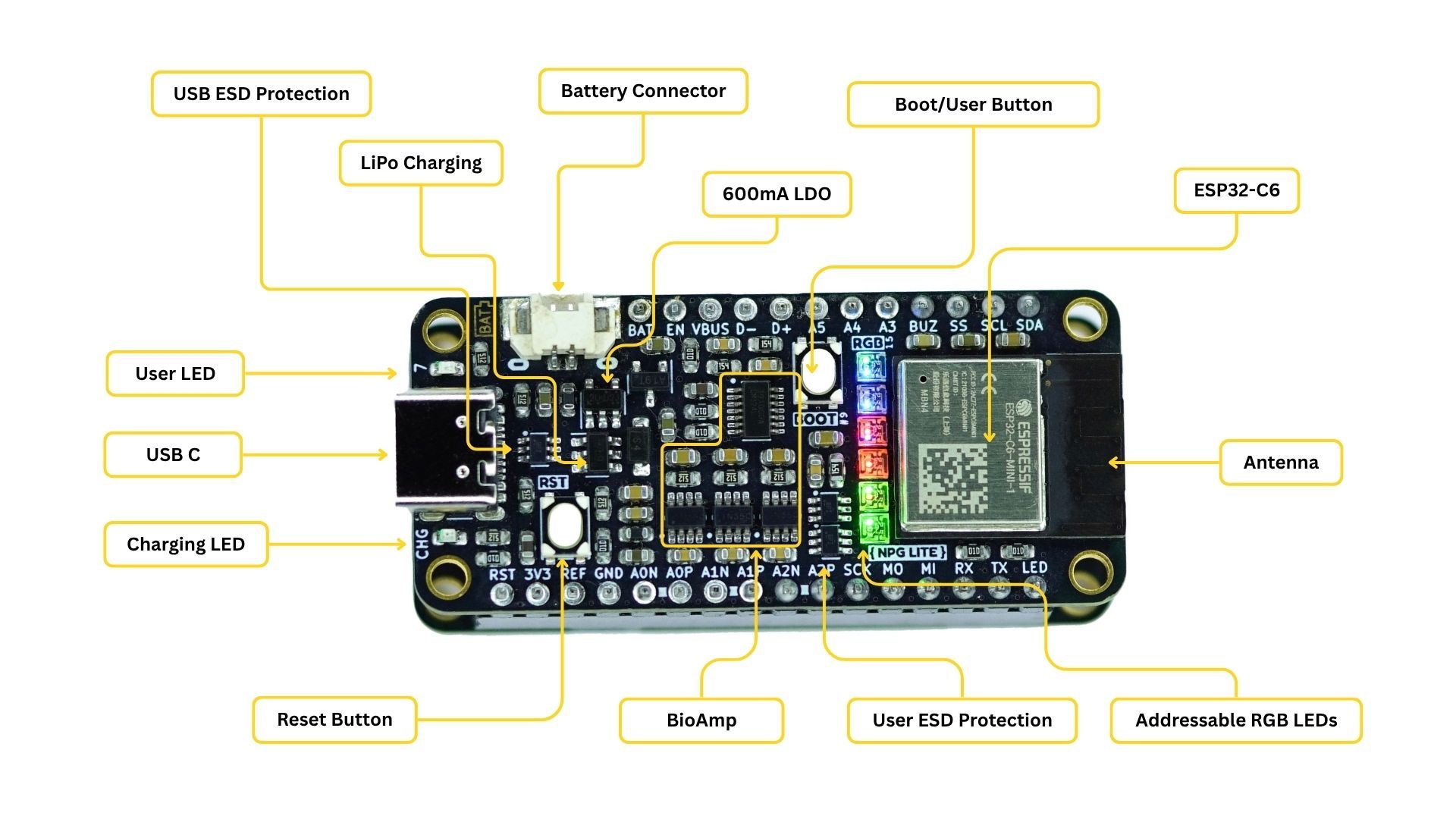
Hardware Specifications
| Component | Specification |
|---|---|
| Microcontroller | ESP32-C6 (RISC-V) |
| Bio-Amplifier | 3-channel on-board (expandable to 6 channels via VibZ+ playmate) |
| ADC Resolution | 12-bit |
| Supported Signals | ECG, EMG, EOG and EEG |
| Wireless | Wi-Fi 6, Bluetooth LE 5, Thread and Zigbee |
| Form Factor | Standard Adafruit Feather |
| Expandability | Playmates or Featherwings |
| Power | USB-C or LiPo battery with on-board charging |
| Protection | ESD protection for BioAmp inputs and USB |
| Visual Feedback | 6x RGB addressable LEDs + User LED + Charhing status LED |
NPG Lite Pinout Diagram
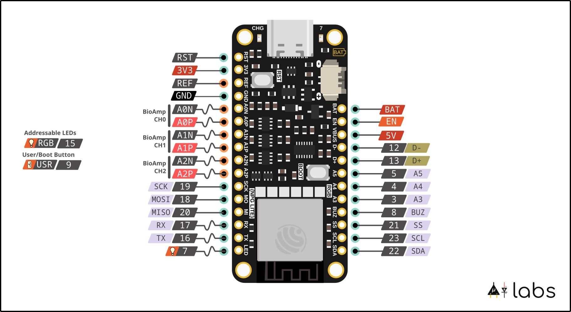
Pin Descriptions
Bio-Amp Input Pins
| Pin | Function | Description |
|---|---|---|
| A0P | CH1+ | Channel 1 Positive |
| A0N | CH1- | Channel 1 Negative |
| A1P | CH2+ | Channel 2 Positive |
| A1N | CH2- | Channel 2 Negative |
| A2P | CH3+ | Channel 3 Positive |
| A2N | CH3- | Channel 3 Negative |
| REF | REF | Common reference electrode (Mid supply) |
| CN | CN | Common Negative Electrode |
Standard Feather Pins
| Pin | Function | Description |
|---|---|---|
| 3V3 | 3.3V Output | Regulated 3.3V power supply |
| GND | Ground | Power and signal ground |
| VBAT | Battery Input | LiPo battery connection |
| EN | Enable | Disable LDO when pulled low |
| USB | USB Power | 5V when USB connected |
| RST | Reset Button | Hardware reset |
| BOOT | Boot Button | Boot/Programmable user button |
GPIO Expansion Pins
| Pin | Function | Description |
|---|---|---|
| SCL(23), SDA(22) | I2C Bus | Clock and data lines |
| SCK(19), MISO(20), MOSI(18), SS(21) | SPI Bus | Serial peripheral interface |
| RX(17), TX(16) | UART | Serial communication |
| 3-5 | Analog/Digital GPIO | ADC capable pins |
| 7(LED) | GPIO | User LED on board |
| 8(Buzz) | GPIO | Buzzer on Playmates |
Power Specifications
| Parameter | Specification | Type |
|---|---|---|
| USB Voltage | 4.7-5.5V | Input |
| USB Current | 350mA | Input |
| LiPo Voltage | 3.7-4.2V | Input |
| LiPo Charging Current | 200mA | Output |
| Operating Current | ~150mA | Input |
| Standby Current | ~15mA | Input |
Choose Your NPG Lite Kit
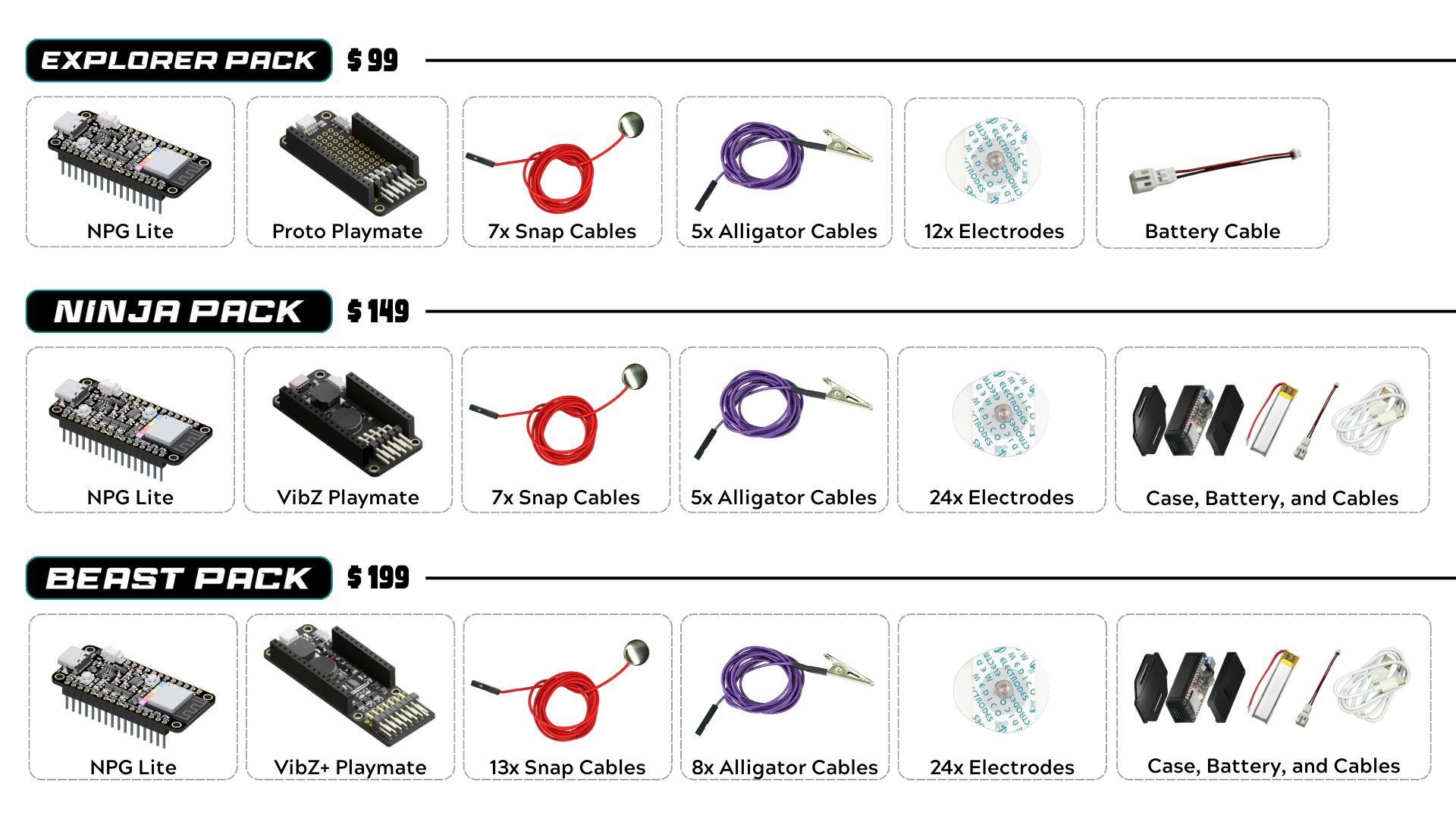
Each NPG Lite kit includes the main board plus a specialized Playmate expansion board that adds unique capabilities. Choose the kit that matches your project needs:
Understanding Playmate Expansion Boards
Proto Playmate (Explorer Kit)
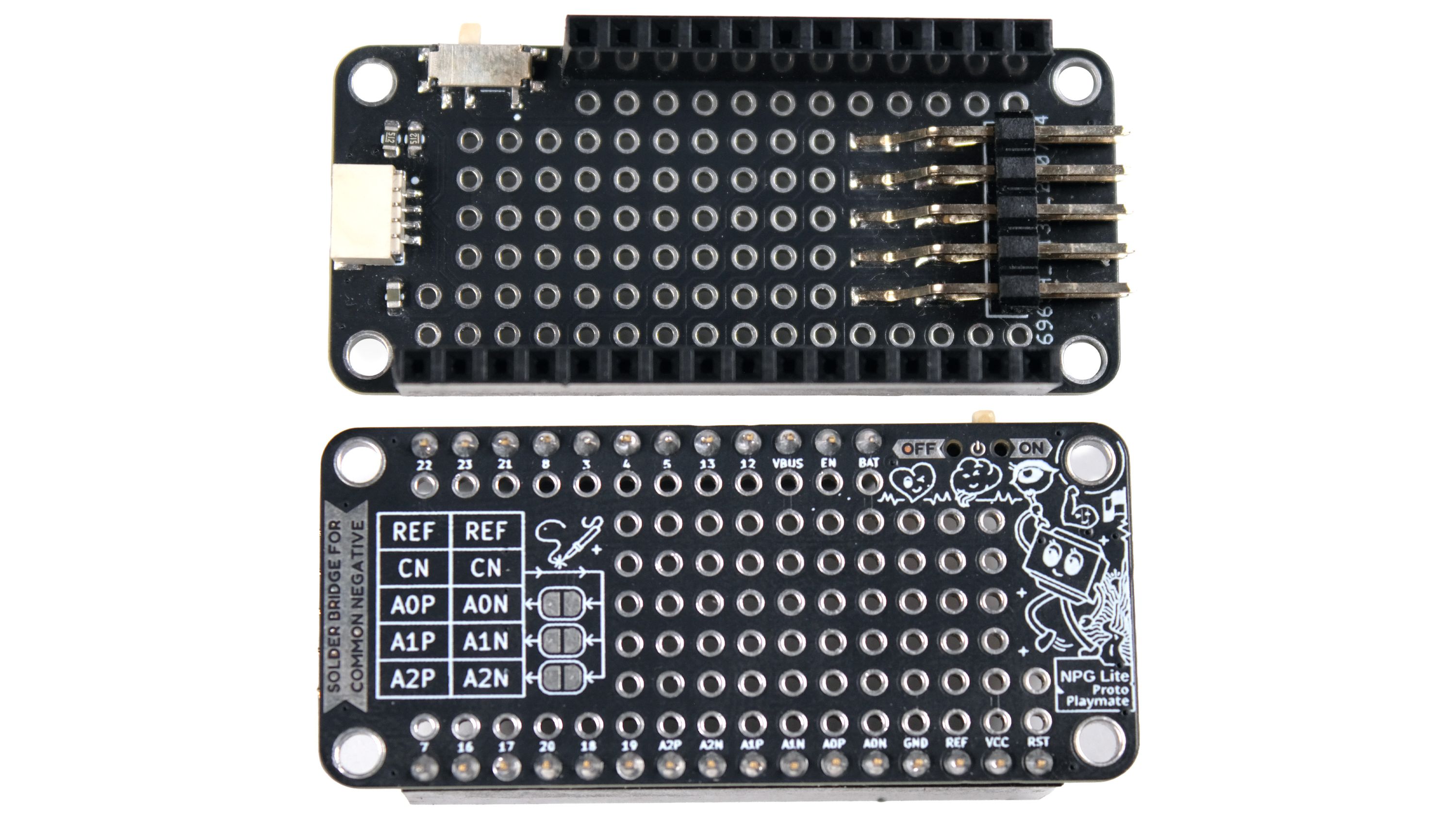
Features:
- Large prototyping area for custom circuits
- Standard 2.54mm electrode headers
- ON/OFF slide switch
- QWIIC port for I2C sensors
VibZ Playmate (Ninja Kit)
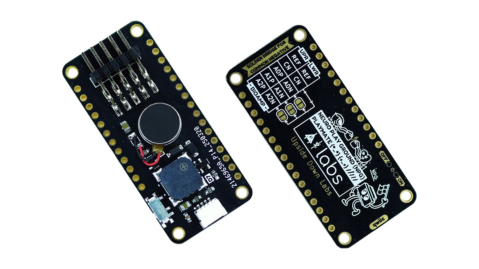
Features:
- Vibration motor for haptic feedback
- Buzzer for audio alerts
- Standard 2.54mm electrode headers
- ON/OFF slide switch
- QWIIC port for I2C expansion
VibZ+ Playmate (Beast Kit)
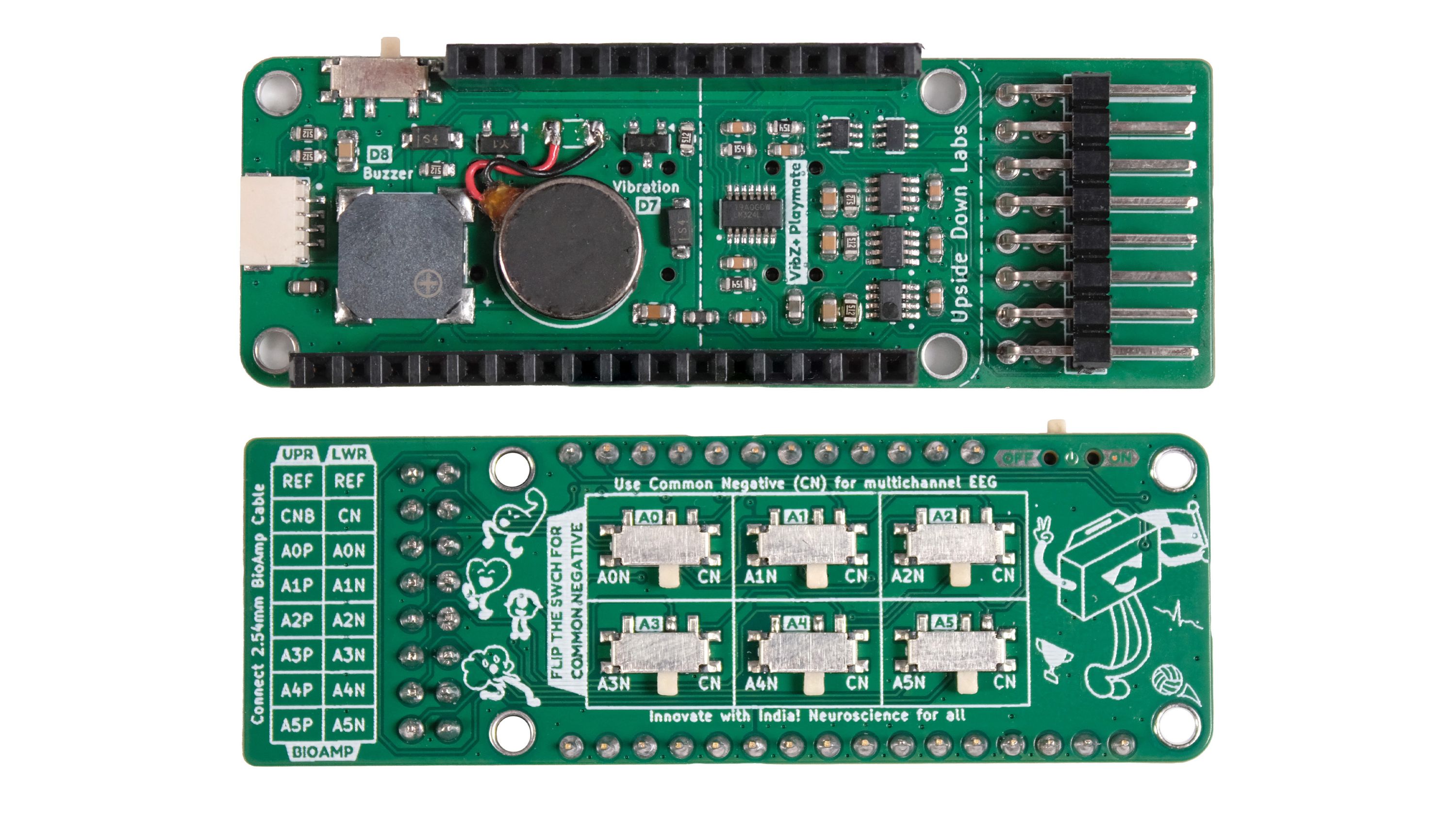
Features:
- All VibZ Playmate features
- Additional 3-channel BioAmp (total 6 channels)
- Standard 2.54mm electrode headers
- Extended electrode connectors
- Toggle switches for Sequential/Referential montage
Playmate Pinout & Connections
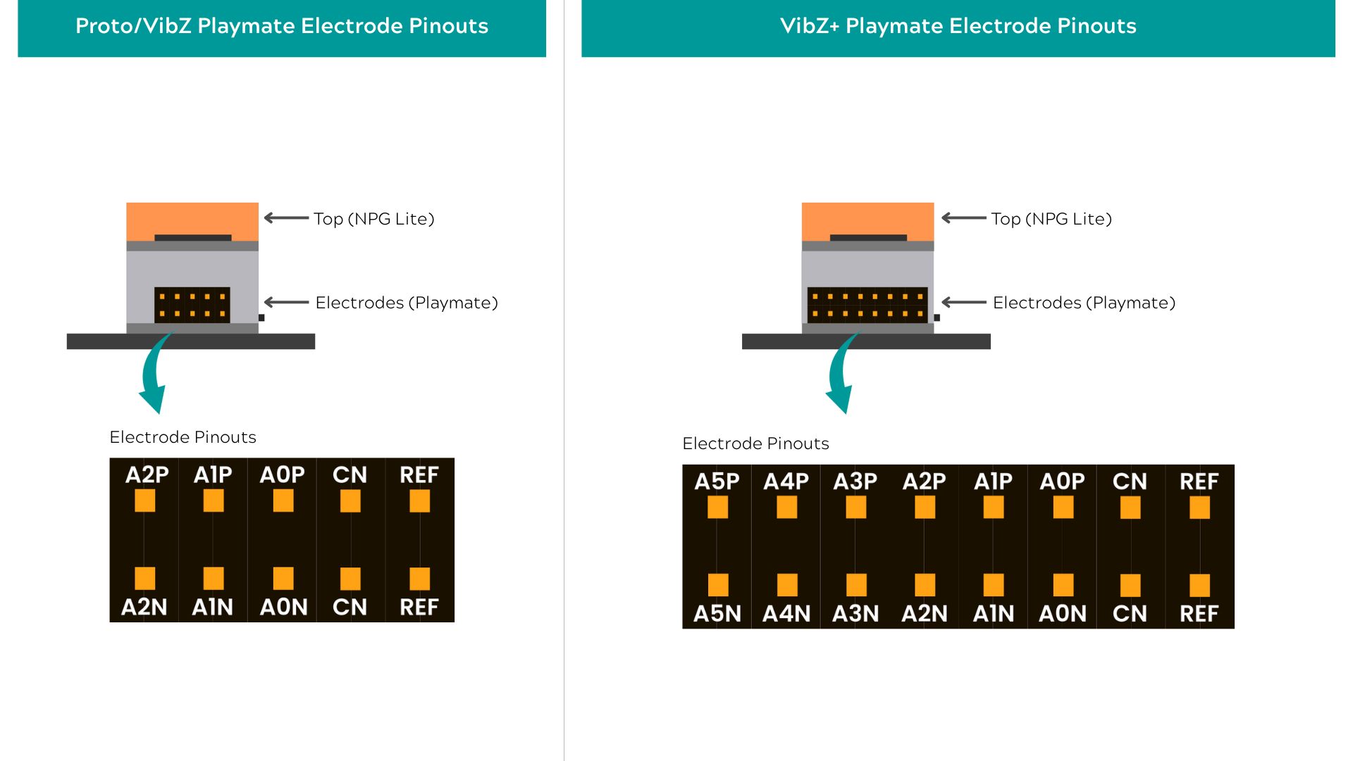
Standard Electrode Connections (All Playmates)
| Pin | Function | Description |
|---|---|---|
| A0P | CH1+ | Channel 1 Positive |
| A0N | CH1- | Channel 1 Negative |
| A1P | CH2+ | Channel 2 Positive |
| A1N | CH2- | Channel 2 Negative |
| A2P | CH3+ | Channel 3 Positive |
| A2N | CH3- | Channel 3 Negative |
| REF | REF | Common reference electrode (Mid supply) |
| CN | CN | Common Negative Electrode |
VibZ+ Additional Channels
| Pin | Function | Description |
|---|---|---|
| A3P | CH1+ | Channel 4 Positive |
| A3N | CH1- | Channel 4 Negative |
| A4P | CH2+ | Channel 5 Positive |
| A4N | CH2- | Channel 5 Negative |
| A5P | CH3+ | Channel 6 Positive |
| A5N | CH3- | Channel 6 Negative |
Playmate Comparison Table
| Feature | Proto | VibZ | VibZ+ |
|---|---|---|---|
| Bio Channels | 3 | 3 | 6 |
| Prototyping Area | ✅ Large | ❌ | ❌ |
| Haptic Feedback | ❌ | ✅ Vibration | ✅ Vibration |
| Audio Feedback | ❌ | ✅ Buzzer | ✅ Buzzer |
| QWIIC Port | ✅ | ✅ | ✅ |
| Power Switch | ✅ | ✅ | ✅ |
| Electrode Headers | Dupont 2.54mm | Dupont 2.54mm | Dupont 2.54mm |
| Common Negative | Solder option | Solder option | Switch |
| Best For | Development | Complete Projects | Research |
Hardware Required
For this tutorial, we’ll be using Neuro PlayGround Lite Ninja pack
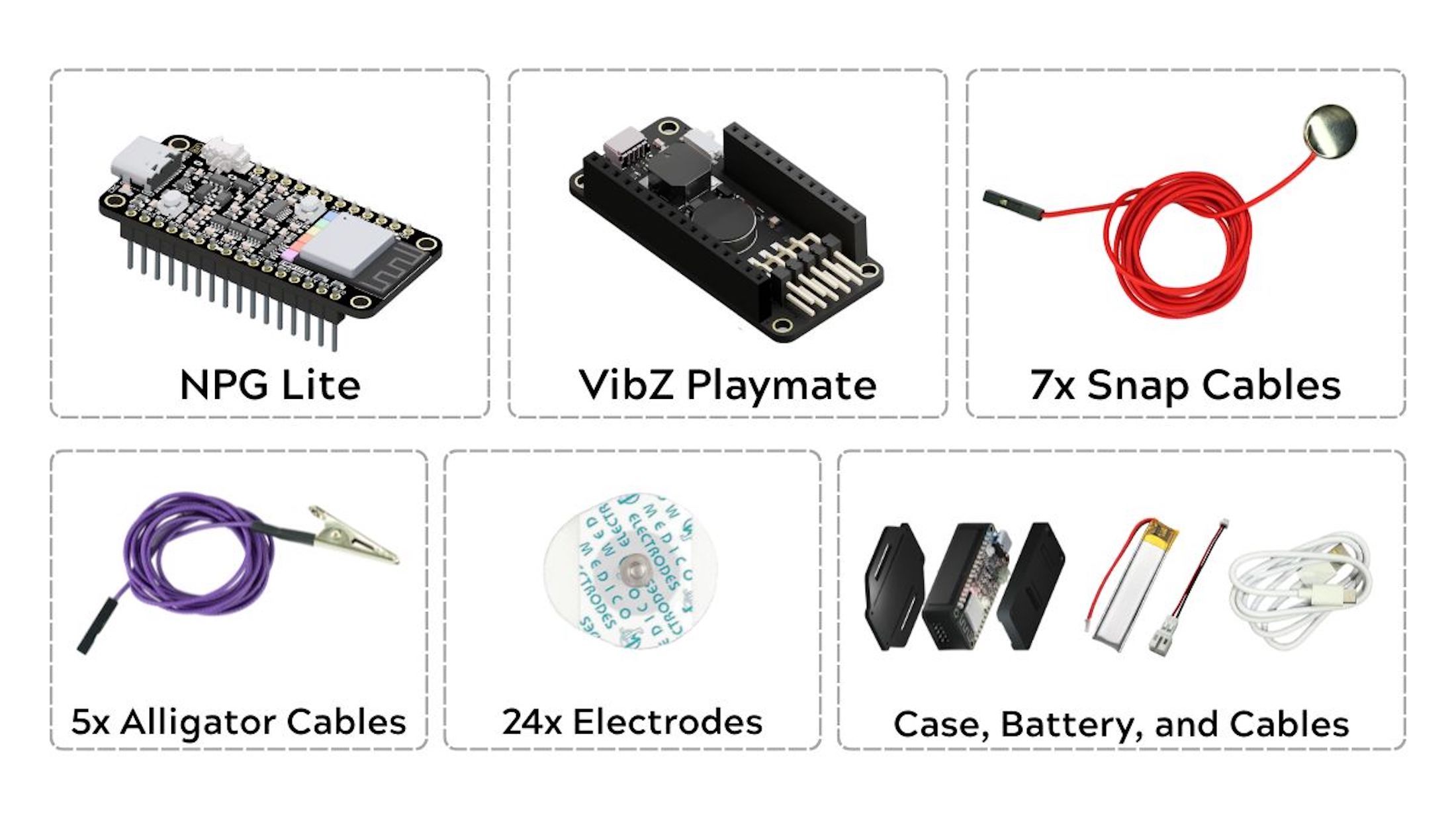
- Neuro PlayGround Lite (ESP32-C6 BioAmp board)
- VibZ Playmate (electrode hub)
- Gel electrodes (3 pcs minimum)
- BioAmp snap cables (3 cables minimum for single channel setup)
- LiPo battery (included in Ninja/Beast packs)
Additional Items
- NuPrep skin-prep gel (Optional)
- Alcohol swabs
- A laptop with USB-C port
Video Tutorial
Follow along with our comprehensive video tutorial:
Additional Resource: Instructables Guide - Your First Steps to HCI/BCI Projects
Step 1: Skin Preparation
First, let’s prepare your skin surface before applying the electrodes.
Preparation Steps:
(Please refer to the images below for electrode placement locations)
- Apply NuPrep Skin Preparation Gel to electrode placement areas
- Clean with alcohol swabs after gel application
Electrode Locations:
- EMG: Flexor carpi radialis muscle (forearm)
- ECG/EKG: Chest or wrist placement
- EEG: Forehead and behind both ears
Step 2: Connection Setup
Time to connect BioAmp Snap Cables to NPG Lite and place electrodes.
Cable Connections:
- Channel 1: A0P and A0N (EMG - forearm)
- Channel 2: A1P and A1N (ECG/EKG - chest or wrist)
- Channel 3: A2P and A2N (EEG - head)
- Reference: One cable for common reference (bony part behind the ear)
Electrode Placement:
⚠️ Important Notes:
- You can use any of the channels for EEG, ECG, EOG, or EMG
- The reference electrode is shown separately in each image below, but we'll be using a common reference(EEG placement) for all channels.
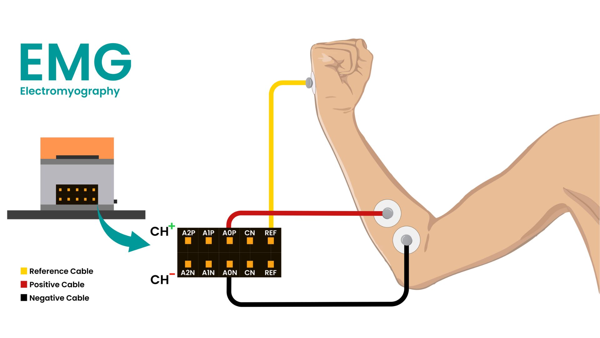
EMG Placement:
- Place positive and negative electrodes on your forearm muscle
- Place reference at the bony part on your hand
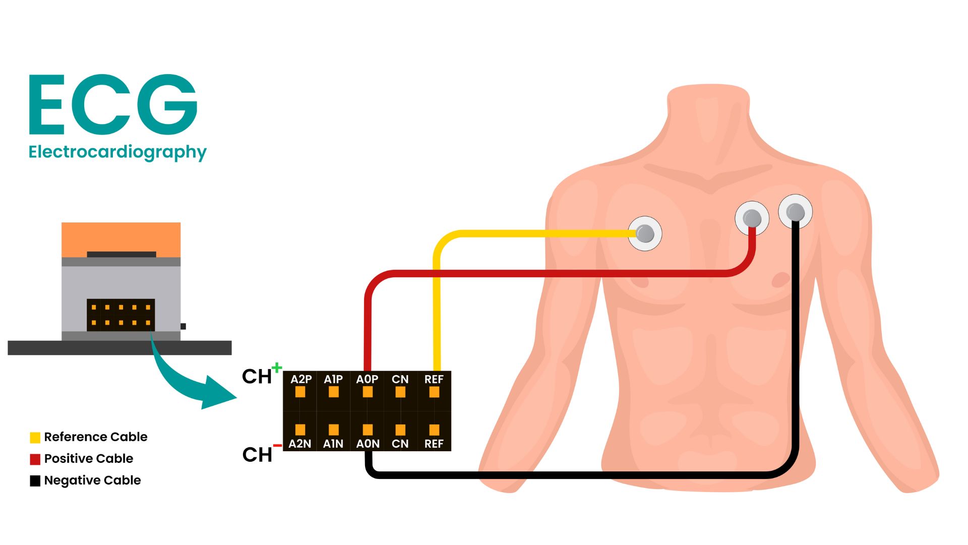
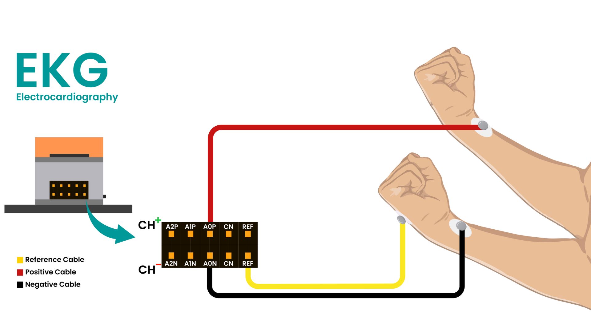
ECG/EKG Placement:
- Negative: Left wrist or chest under left arm
- Positive: Right wrist or chest under left arm
- Reference: Bony part on your hand or chest under right arm
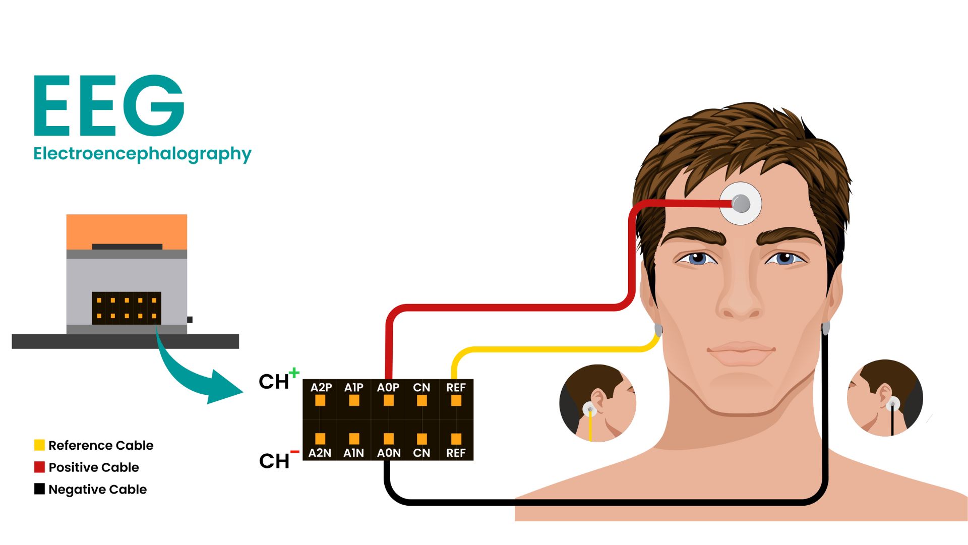
EEG Placement:
- Positive: Forehead (between FP1 and FP2)
- Negative: Behind one ear (bony part)
- Reference: Behind the other ear
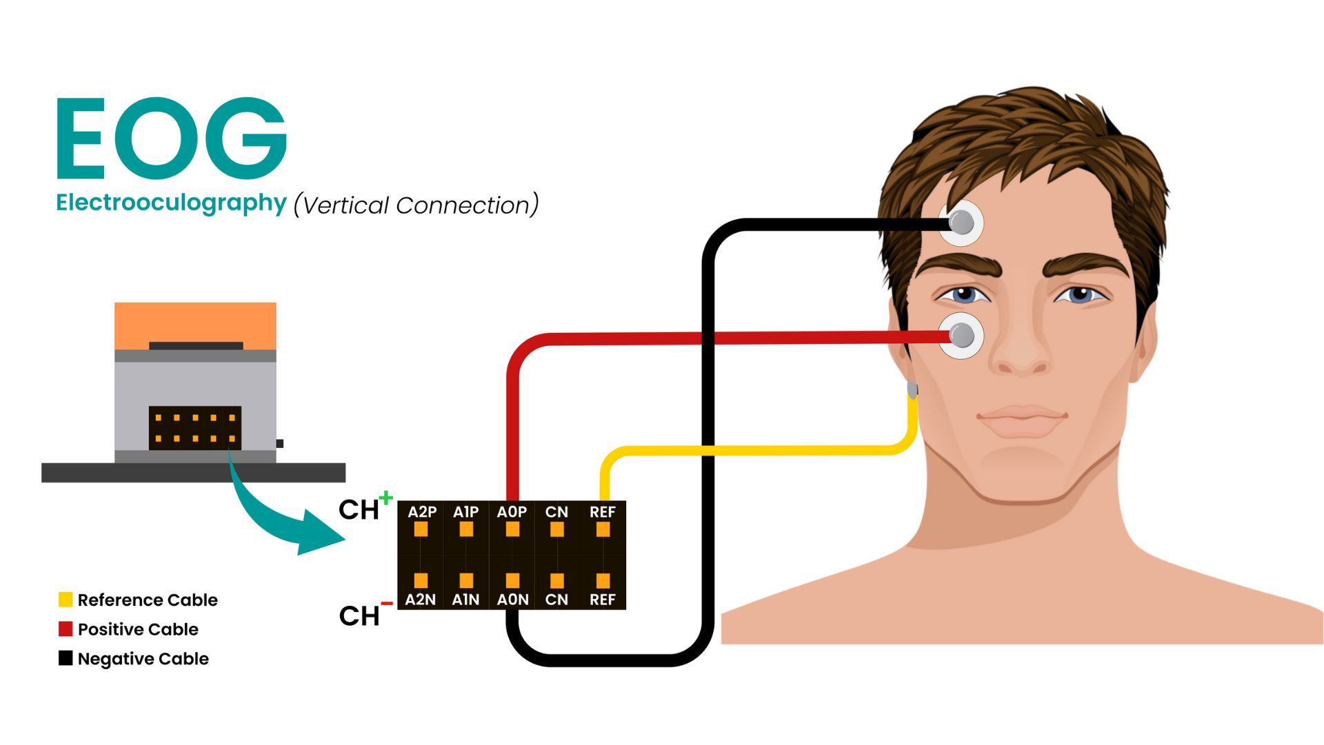
EOG Placement:
For future EOG projects, refer to the placement image below:
- Positive: Above any eye
- Negative: Below any eye
- Reference: Bony part behind the ear
Step 3: Pre-Visualization Checks
Before starting data visualization, ensure:
Checklist:
- [ ] Skin is thoroughly prepared
- [ ] Laptop is NOT connected to charger
- [ ] You're at least 5 meters away from AC appliances
- [ ] All electrodes are properly placed and connected
- [ ] NPG Lite is fully charged and powered-ON
Step 4: Power On Your NPG Lite
Now, let’s fire up the NPG Lite by toggling the switch on the VibZ Playmate.
Step 5: Flash the Firmware
We’ll use the NPG Lite Flasher, a user-friendly tool to flash firmware onto your ESP32-based NPG Lite.
Download the Flasher
- Download the NPG Lite Flasher from: github.com/upsidedownlabs/NPG-Lite-Flasher
- Install and launch the application
Flash the Firmware
- Connect your NPG Lite via USB-C cable
- Choose the firmware you'd like to flash:
- BLE (for this tutorial)
- Wi-Fi
- Serial
- Custom
- Identify the correct port
- Click "Flash"
After Flashing
Once the firmware is flashed:
- Unplug the NPG Lite from your laptop
- Disconnect the laptop's charger to minimize AC noise
LED Status Indicators (Chords BLE Firmware)
The NPG Lite features RGB LEDs that provide visual feedback for connection status:
- 🔴 Red LED: Device is powered on but disconnected
- 🟢 Green LED: Device is connected to Chords interface
- 🔵 Blue LED: Device is connected and actively streaming data
Haptic Feedback (VibZ/VibZ+ Playmates)
The VibZ and VibZ+ Playmates also provide vibration feedback:
- Single vibration: Device successfully connected
- Double vibration: Device disconnected
Step 6: Data Visualization
Finally, let’s visualize your bio-signals!
Open Chords Web Interface
- Click on Chords-Web on NPG Lite Flasher
- or, Go to: chords.upsidedownlabs.tech
Use a Chromium-based browser (Chrome, Edge, etc.)
Connect Your Device
- Click "Visualize Now"
- Select "NPG-Lite" from the bottom options
- Ensure Bluetooth is enabled (no manual pairing needed)
- Click "Connect" to scan for devices
- Select your NPG Lite from the list
Configure Channels & Filters
- Click the settings icon to select all channels
- Apply appropriate filters:
- Channel 1: EMG filter
- Channel 2: ECG/EKG filter
- Channel 3: EEG filter
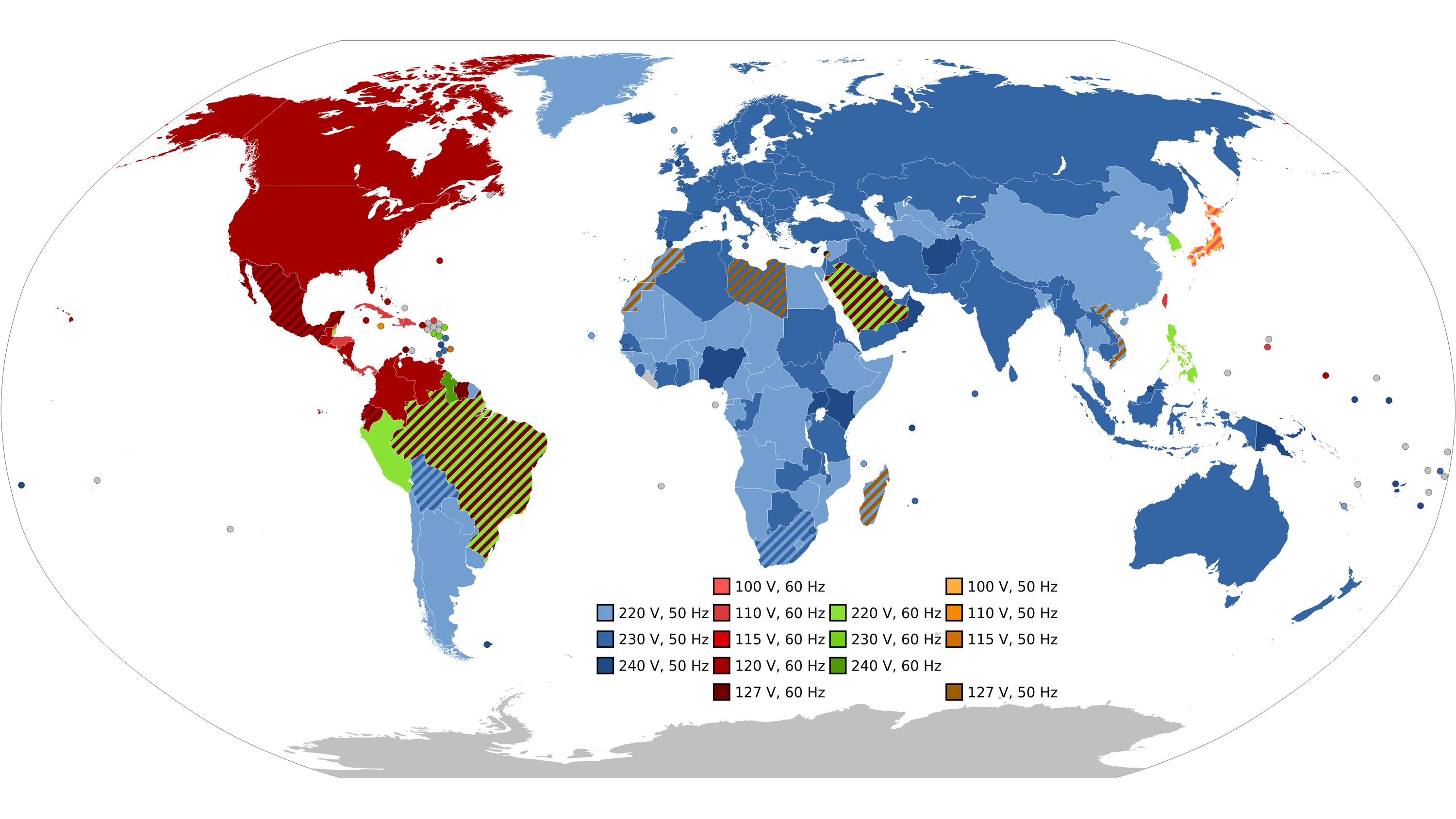
- Enable notch filter (50Hz or 60Hz based on your region)
Interface Features
This interface allows you to:
- ✅ Select channels you'd like to visualize
- ✅ Adjust zoom level for better signal viewing
- ✅ Play/pause the data stream for analysis
- ✅ Apply bandpass filters and notch filters
- ✅ Record data for all channels and save in CSV format
When you’re done, click "Disconnect".
Troubleshooting
Common Issues & Solutions
Device Not Connecting
- Check USB-C cable connection
- Install ESP32 drivers if on Arduino
- Try different USB port
- Try putting your device to BOOT mode (BOOT + RESET) to flash the firmware
Poor Signal Quality
- Clean skin with alcohol wipes before electrode placement
- Press electrodes firmly to ensure good gel contact
- Minimize movement during recording
- Check all connections are secure
- Make sure you're at least 5 meters away from AC appliances
Bluetooth Issues
- Bluetooth should be enabled on the system
- Ensure BLE firmware is flashed correctly
- Check device is powered on (LED indicators)
- Clear browser cache and reload
- Move the device closer to the system (within 10 meters)
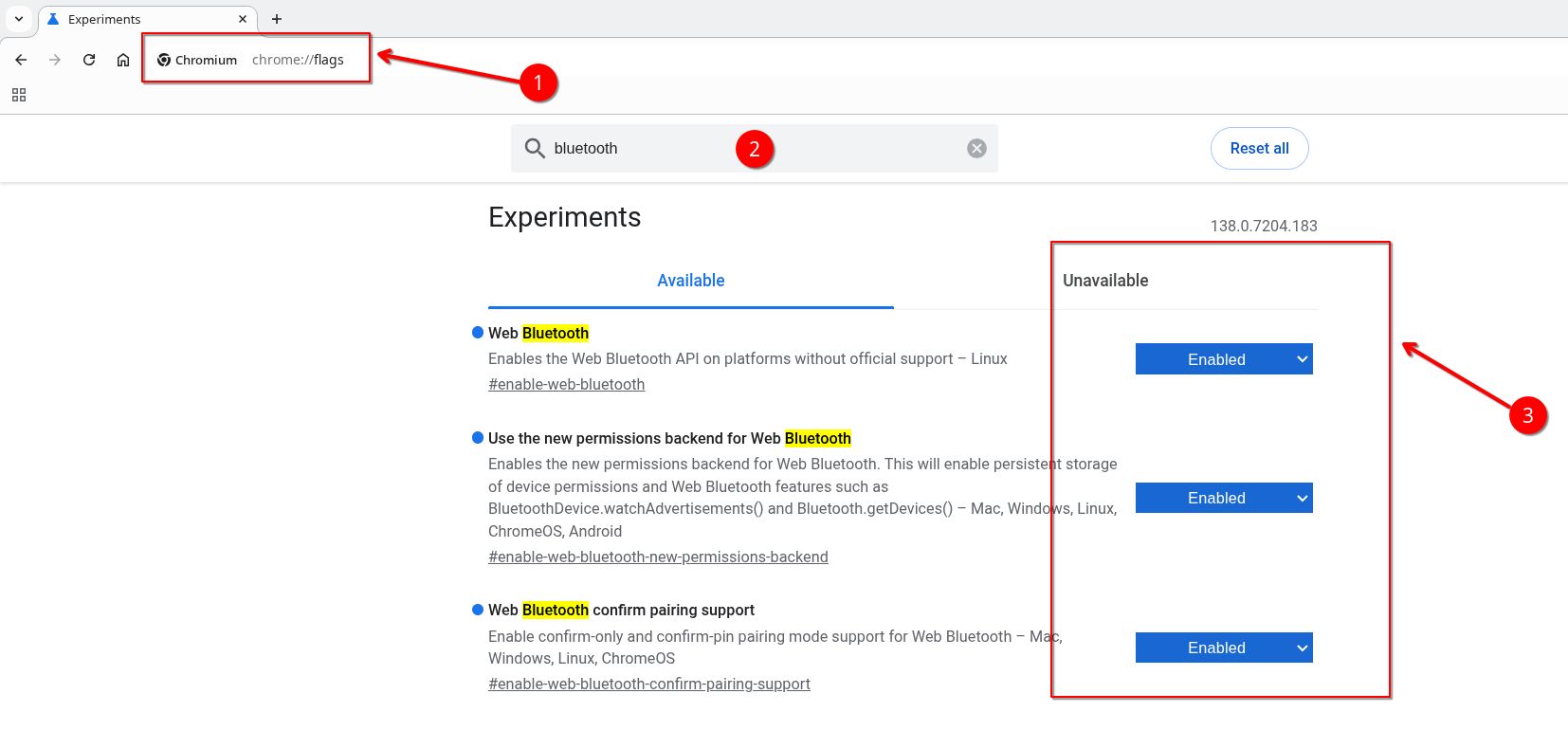
If you still face issues connecting to your device via bluetooth, follow these steps and try again:
- Go to you chromium based browser
- Type chrome://flags in the search bar and hit enter
- Search for Bluetooth and enable everything related to Web Bluetooth
- Restart your browser
- Try connecting again
Safety Guidelines
⚠️ Important Safety Notes
- Never exceed 3.3V input on GPIO pins
- Single-use electrodes: Don't share between users
- Medical disclaimer: Not for medical diagnosis or treatment
- Keep away from liquids and operate within 0-40°C (32-104°F)
What’s Next?
This concludes the NPG Lite Getting Started Tutorial, Get Yours today!
Learn More:
- Official Documentation: docs.upsidedownlabs.tech
- Join our Discord: discord.gg/SzYRVz8xRw
- GitHub Projects: github.com/upsidedownlabs
Keep experimenting and building amazing HCI and BCI projects! 🚀